Reference · Italy · 2024
SNCR revamping with offset spray: 3.5 MW biomass boiler – Italy
Revamping of an SNCR system built by Ecotherm in 2017. The new boiler has a cylindrical combustion chamber: to stop the urea jets from colliding at the centre, we redesigned the injection lances with an offset spray.
The project
In 2017 Ecotherm built the urea SNCR system for this biomass plant near Potenza. In 2024 the boiler was replaced and the NOx reduction system was upgraded with a revamping.
The urea tank, metering pumps and cooling blower were checked and reused. We rebuilt the control panel with a new PLC, added automatic preparation of the urea solution and supplied new injection lances, designed for the geometry of the new boiler.
Why an offset spray
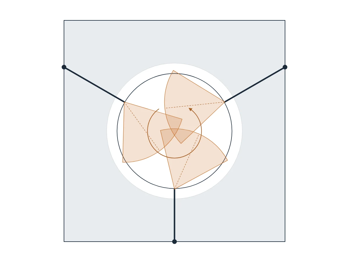
Horizontal section of the post-combustion chamber, simplified and not to scale.
The problem with opposed jets
The maker of the new boiler provided three injection points at 120° around a cylindrical chamber. With on-axis jets aimed at the centre, the three urea sprays would have overlapped in the same zone: too much reagent in one spot, local cooling of the flue gas and part of the section poorly reached by the urea.
Jets turned in the same direction
Each lance enters perpendicular to the wall, but the jet leaves turned away from the centre of the chamber, all in the same direction. The sprays spread along the circumference instead of colliding: they improve turbulence and mixing with the incoming flue gas, and the reagent covers the whole section of the chamber better.
Three lances instead of two
The first system worked with two straight-spray lances. The new boiler was designed with three injection points: the lances follow the geometry set by the boiler maker.
The result
The three lances were fitted in the planned injection points, with no changes to the boiler. At start-up the system met both the 300 mg/Nm³ NOx limit and the residual ammonia limit.
Further reading
Why in a retrofit it pays to angle the jet rather than the port is explained in our offset spray insight; the basics of the technology are in our SNCR and SCR guide.
Scope of supply
- Injection lances: 3 twin-fluid lances with offset spray, flow meters and pressure gauges
- Control panel and PLC: modification of the existing panel, new PLC with 4–20 mA control and NOx normalised to the reference oxygen
- Urea preparation: automatic dilution by weight with load cells, transfer and recirculation pump
- Piping: stainless steel where in contact with urea, atomising and cooling air lines
- Existing components: insulated urea tank, metering pumps and blower checked and reused
- Installation, start-up and staff training
- Mounting flange on the boiler wall
- Urea, atomising air and cooling air inlets
- Nozzle with an air cap that turns the jet
Simplified drawing, not to scale.
The lances
How the lances are built
They are twin-fluid lances: urea flows through the centre of the lance and compressed air atomises it into fine droplets at the nozzle.
The air cap turns the jet away from the lance axis. The lance is mounted perpendicular to the wall, in the port provided by the boiler maker, and the jet already leaves in the right direction: so no changes to the boiler were needed.
A cooling air circuit, with a dedicated blower, protects the lance from the temperature of the combustion chamber.
Need to adapt an SNCR system to a new boiler?
Send us the boiler data and details of your existing system: we will assess together what can be reused and what needs rebuilding.